We present hereafter a reference example for the Switched Ethernet Flows Analysis. The objective is to compute the Worst Case Transmission Time (WCTT) of packets sent on a switched Ethernet network such as AFDX networks in avionics systems.
This presentation is decomposed in two parts:
- a presentation of a subset of the AADL – AFDX property set, which is used to set up network properties used in the analysis
- a presentation of the reference example itself, with its structure and use of the AFDX properties
If you want more details about the mathematical equations used in this analysis plugin, please refer to the following paper, which presents the trajectory approach [1]
Useful subset of the AADL – AFDX property set
The AADL – AFDX property set has been defined in the scope of the preliminary definition of a “network annex” to the AADL. The SAE AADL standardisation subcommittee conducted this work, which was initiated by ISPRAS (Institute for System Programming of the Russian Academy of Sciences).
We list hereafter the set of properties we use to characterise an Ethernet switched network and apply the trajectory approach [1]. After this presentation, we sum up in table 1 the correspondence between these properties and the concepts used in [1]. This way, one can understand better how the AADL – AFDX properties are used to compute WCTTs using the method presented in [1].
The meaning of the properties is given as comments in the properties definition.
-- Speed of the physical port
portSpeed :    inherit Data_Volume
               applies to (device,system,bus access);

-- Minimum VL frame size
Lmin :    AADLINTEGER 64 Bytes .. 1518 Bytes
          units SIZE_UNITS => 64 Bytes
          applies to (virtual bus);

-- Maximum VL frame size
Lmax :    AADLINTEGER 64 Bytes .. 1518 Bytes
          units SIZE_UNITS
          applies to (virtual bus);

-- BAG - Bandwidth Allocation Gap
-- The End-System controls the transmission flow for each VL
-- in accordance with the BAG (traffic shaping).
-- The Switch should verify the BAG (traffic policing).
BAG :     TIME applies to (virtual bus);

Deadline: TIME applies to (virtual bus);

-- An output port should not transmit frames that are older than "max delay".
-- The maximum delay parameter of a frame on a given port is defined as the maximum elapsed time between the two following events:
   -- 1. Arrival of the last bit of a frame on the input port of a switch
   -- 2. Exit of this last bit of the frame from the given output port of the switch
maxDelay : inherit TIME applies to (bus access,device,system);
Reference example
How to import the project in your workspace?
From OSATE, make sure you installed the SEFA (Switched Ethernet Flow Analysis) plugin. Installation instructions are here. If the SEFA plugin is installed, click on “File –> New –> Example…” select “SEFA/SEFA Examples” and click on “Finish”. Two projects are added to your workspace: “reference_example” and “industrial_example”. In the remainder of this page, we work with the “reference_example” project.
How to start the analysis?
First instantiate the system implementation called main.impl in file SwitchedEthernetNetworkExample.aadl: select main.impl in the “outline” view of OSATE (usually on the right side of OSATE), right click on main.impl and select “Instantiate system”.
This action created an instances directory called “instances”, as you can see in your project folder inside the AADL Navigator (usually on the right side of OSATE). In this folder, select file “SwitchedEthernetNetwork_main_impl_Instance.aaxl2″ and in the main menu (at the top of OSATE) click on SEFA and select “Switch Ethernet Flows Analysis“.
As a result of the analysis, an xml file with extension .ares is generated. Open it to see the analysis results.
Description of the example
The reference example presented hereafter is made up of 4 end systems, 3 switches and 6 ethernet wires. We present hereafter the definition of :
- the hardware platform,
- the packets paths,
- the network properties.
1. Hardware platform.
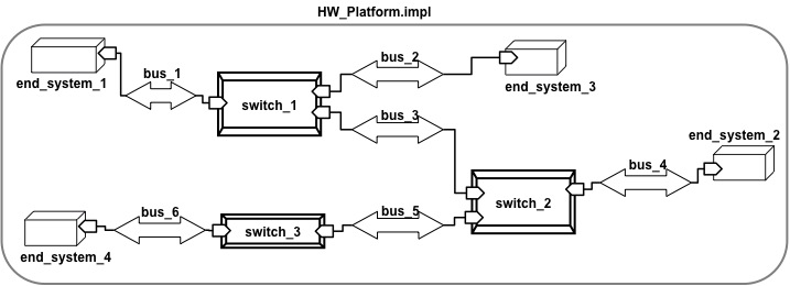
Figure 1: Hardware platform of the reference example
In the reference example, the hardware platform is defined in a system implementation called HW_Platform.impl. Figure 1 provides the AADL graphical representation of this component. As we can see, it is made up of 6 bus subcomponent (bus_1 to bus_6), 3 device subcomponents (switch_1 to switch_3), and 4 processor subcomponents (end_system_1 to end_system_4). These components are connected via bus accesses as illustrated on figure 1.
Processor subcomponents represent the computation unit from which packet are sent, or in which packets are received. A required bus access represents a physical port of the computation unit, to send or receive packets.
Device subcomponents represent ethernet switches on which packets are routed. Here also, a required bus access represents a physical port of the switch.
Bus subcomponents represent ethernet wires that connect computation units to switches, and switches to switches.
2. Packets paths
In addition to the network itself, presented in the previous section, we need to represent packets path in this network. In AADL, a network route can be represented with a virtual busses, and its binding to a list subcomponents in the network. For those who know about AFDX networks, a virtual bus here represents an AFDX virtual link.
In the reference example, 3 virtual buses are defined (flow_1 to flow_3).
Figure 2 provides a graphical representation of flow_1.
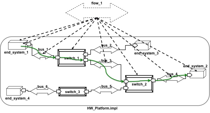
On this figure, we represented in green the route of packets of flow_1. In terms of AADL, this is represented as an ordered list of network components with the property Actual_Connection_Binding applied to flow_1. This is graphically represented by the dashed arrows and the corresponding AADL code is given here:
-- path for flow 1
Actual_Connection_Binding => ( reference (HW.end_system_1),
                               reference (HW.bus_1), reference(HW.switch_1),
                               reference(HW.bus_3), reference (HW.switch_2),
                               reference(HW.bus_4),
                               reference (HW.end_system_2) )
                             applies to flow_1;
3. Network properties
Last but not least, the packet flows must be characterised in terms of bandwidth usage, time to traverse a switch, a bus, etc.
This is done using the properties defined in section “Useful subset of the AADL – AFDX property set” at the beginning of this page.
Here is the AADL code for characterising flow 1:
AFDX_Properties::portSpeed => 100 MBytesps;
AFDX_Properties::Lmin => 100 Mbyte applies to flow_1;
AFDX_Properties::Lmax => 100 Mbyte applies to flow_1;
AFDX_Properties::BAG => 36 ms applies to flow_1;
AFDX_Properties::Deadline => 54 ms applies to flow_1;
AFDX_Properties::maxDelay => 4 ms applies to HW.switch_1,HW.switch_2;
Correspondance between AADL models and the theoretical background of the trajectory analysis [1]
Table 1 provides a synthetic correspondence between concepts used in the trajectory aproach [1] and AADL modelling elements.
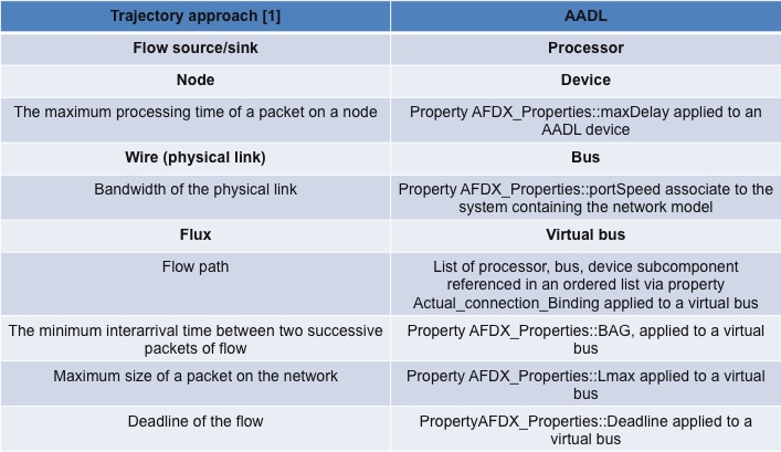
Table 1: relations between AADL and the trajectory approach [1]
[1] Worst case end-to-end response times of flows scheduled with FP/FIFO. S.Martin, P.Minet. In Proceedings of the International Conference on Networking, International Conference on Systems and International Conference on Mobile Communications and Learning Technologies (ICNICONSMCL’06)
Implemented version in the SEFA plugin:
[2] Improving the Worst-Case Delay Analysis of an AFDX Network Using an Optimized Trajectory Approach. H.Bauer, J.-L.Scharbarg and C.Fraboul. In IEEE Transactions on Industrial Informatics.