The slides of the introduction to AADL are available here.
Tools Presentation
The tools you are going to use during this exercise are (tools are already installed on your virtual machine, so we just put the links for information):
- OSATE, an AADL editor and analysis environment (http://osate.org/)
- RAMSES, a model transformation and code generation tool integrated with OSATE (https://mem4csd.telecom-paristech.fr/)
- AADL Inspector, an AADL editor and tool suite including timing analysis capabilities (https://www.ellidiss.com/products/aadl-inspector/)
The application will be executed on a NXT robot (https://en.wikipedia.org/wiki/Lego_Mindstorms_NXT), on which the nxtOSEK operating system (http://lejos-osek.sourceforge.net/) has been installed.
Initial Design
An initial AADL design of the application, almost complete, is available here.
How to import the AADL project into OSATE:
- Launch OSATE , the application is installed on the virtual machine, here: ~/tools/osate2/osate
- If not done yet, download the initial AADL design (here).
- Unzip the archive file of the initial AADL design.
- Import the initial AADL design in OSATE: in the menu, click on File -> Import…
- Select General -> Existing project into workspace -> Next
- Select the directory with the initial AADL design (result from step 3.)
- Finalize import (click Next until Finish)
–> Result: you should have an AADL project named “line-follower” in your OSATE workspace now.
You can navigate through the project to start understanding the design. The easiest way to start is probably to use the graphical editor as it provides a first synthetic view on the architecture. Graphical editor files are stored in the diagrams folder. You can open the one we have prepared for you: lineFollower_LightSensor.aadl_diagram
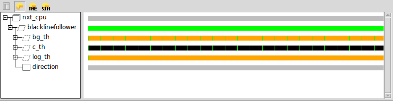
Let us describe the structure, which contains:
- The root AADL system implementation definition (named lineFollower.LightSensor)
- The hardware platform definition, made up of a processor and memory subcomponents respectively named nxt_cpu and nxt_mem
- The software application defined as an AADL process subcomponent (named BlackLineFollower) made up of:
- A global variable (AADL data subcomponent) named Direction
- Three thread subcomponents named Bg_th, C_th, and Log_th (respectively for getting the light sensor value, control the line follower robot and log the PID controler inputs/outputs).
Textual files contain details that cannot be seen on the architecture diagram. You can open the textual definition of a component from the graphical editor: for instance, select the thread subcomponent named C_Th, right click on it, and select “Open AADL source”.
You are now on the definition of the thread subcomponent. Its implementation is ContrThread.impl. In the textual AADL editor, you can use “Ctrl+click” to navigate through model elements. For instance, do a “Ctrl+click” on ContrThread.impl
You are now on the definition of the thread implementation itself. In this definition, property values have been associated to the thread :
- The Dispatch_Protocol property value makes the thread periodic: the code of this thread will be executed periodically
- A Period property defines how often the thread is executed.
- A Priority property defines the relative priority of the thread.
- A Compute_Entrypoint_Call_Sequence defines the sequence of subprograms that will be executed when the thread is dispatched. You can have a look at the subprograms definition, in which you will find references to C functions and source files. Do not hesitate to open them to better understand the application.
Tips:
- Yellow arrows in the toolbar (
 ) help you to go navigate to/from locations you were looking at in a recent history.
Part 1: Basic Model Editing
In this first step, you are going to try to generate code and deploy the initial design on the robot. Note that aadl source files are stored in the aadl_src folder and c files are stored in the c_src folder.
Code generation, first try
To do so, open file “line-follower-light.aadl”. In the outline view (on the right side of the editor), select the system implementation named “lineFollower.LightSensor”. Right click on it (still in the outline view) and click on “launch RAMSES”.
A new window opens to configure RAMSES.
- Select “OSEK/NXT” as a target
- Click on “Choose target platform path” and select folder /home/ttool/nxt/nxtOSEK
- Click on Apply and close
An error message appears saying :
RAMSES execution failed with 1 error(s)

  <Internal Error> Called subprograms must have a behavior annex or reference existing source code (Source_Name and Source_Text properties) in line-follower-light.aadl at line 40
Error Fix
Fix the model using the Source_Name property. Navigate to the subprogram implementation by control clicking on the subprogram type to navigate to its definition at line 23 of file line-follower-subprograms.aadl. See the Source_Name property on the above computePID subprogram. You can see the definition of the property by control clicking on it with. A comment describes the property.
After completing the model, relaunch RAMSES. You probably think it took a long time to execute, but look at what RAMSES has produced:
- An intermediate AADL model (in the refined-model folder). This model includes a representation of the generated code and can be analyzed to make sure software application fits in terms of memory and processor utilization.
- The C files to activate software functions and to implement communications among them located in the generated-code directory
- The build system (Makefiles and operating system configuration files) to produce executable binaries
- The binary files themselves, by calling the make tool.
Upload the code and have fun
Now, you can upload the executable binary file on the robot to run the line follower.
How to upload a file on the brick:
- Connect the NXT brick to the computer with the USB cable
- Switch on the NXT brick by pressing the orange button
- In the VirtualBox menu, click on “Devices -> USB -> Lego Mindstorm NXT“
- In the virtual machine open a terminal and run:
$ cd <path-to-line-follower-folder>/generated-code/nxt_cpu/BlackLineFollower
$ sudo ~/nxt/deployment_tools/NeXTTool /COM=usb -download=BlackLineFollower_OSEK.rxe

(password is: mpm4cpspisa)
It should take about 4 seconds to upload the code. Note that no error message will be displayed in case of failure. To check if the upload was successful, see if the software file on the brick as follows:
- Switch on the brick (orange button)
- Select “Files” (validate with the orange button), “Software files” (validate); see if file “BlackLineFollower_OSEK” is displayed (if you stay on “Software files”, or don’t find the BlackLineFollower_OSEK it means the upload failed: make sure you rigorously followed instructions 1. to 4. in order 😉 )
- Go in the experimentation room to run the robot on the “map of the world”.
How to setup the logging interface
To access your experiment logging data it is necessary to execute the following steps:
1. Connect to the EPresence_8 wifi network. The Wifi key is PaTi2789-x
2. Establish an SSH session between your laptop and the Raspberry assigned to your team’s track: all the Raspberries are numbered, and the corresponding IP Address is available in the logging.txt file.
command to execute: ssh pi@<IP_ADDRESS_OF_YOUR_PI>
3. Establish communication between your team’s NXT Robot and the Raspberry Pie. Check your team’s robot Bluetooth device address that is available in the logging.txt file and execute the following command line command:
sudo rfcomm connect hci0 <BLUETOOTH_ADDRESS_OF_THE_ROBOT>.
When the connection is established the robot the message [R[BT] is presented on the robot’s screen.
4. Start the logger program by executing the following command:
sudo python3 logger.py
5. Start the execution of the Lego line follower program.
6. To terminate the line follower program press the grey button that is below the robot’s orange button.
6. Terminate the logger program execution. Type Ctrl + c.
7. Three files are generated: a CSV file containing the log entries. Each log entry has three fields: the PID output value that will be used to set the motor’s power, the difference between the polled light sensor read and the line’s edge light value and a third value representing the timestamp. Two charts are also generated: one presents the difference between the polled light sensor read and the line’s edge light value and the the PID output value during the test period.
8. Terminate the SSH session by typing exit on the console.
9. To download the variation execute the following command :
scp pi@<IP_ADDRESS_OF_THE_PI>:/home/pi/*.png /home/ttool/Desktop
You can then visualize the figures.
You should observe that the robot is not working properly… To help you understand why, we should check if the system is properly dimensionned.
Part 2: Timing Performance Analysis
There has been an error in releasing the virtual machine thatyou are using so you will need to patch some files for AADL Inspector. First download the patch here. Unzip the files in directory /home/ttool/tools/aadlinspector/AADLInspector-linux64/config/plugins/ of your virtual machine. Make sure that the provide files replace the existing ones.
Let’s have a look at threads scheduling to have a better understanding of functions execution. We will use AADL Inspector for this, a commercial tool we can use with its trial license.
How to launch AADL Inspector from OSATE:
- Open file line-follower-light.aadl. In the outline view, right click on the system implementation lineFollower.LightSensor.
- Select “Launch AADL Inspector”
- Select “Graphical User Interface”
- Set the install directory to /home/ttool/tools/aadlinspector/AADLInspector-linux64
Once AADL Inspector is launched, you can do schedulability tests (check if the deadlines of the treads will be met).
On the right side of the tool, select Timing Analysis
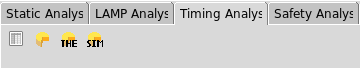
- Click on the Cheese icon (Yes, it is a tool from a French company, French people love cheese …)
- Click on the Cheese icon with THE on it. open the diagnostic to understand the error.
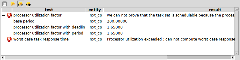
Observations: the system is not schedulable
Propose a solution, and test it: how to reduce the cpu load? Modify the model (from AADL Inspector and not in OSATE), and make sure the system is schedulable with your modifications. Note: you cannot change the execution time of the threads, this has been estimated by measuring the timing execution of the object code on the brick. However the period of the threads is a good place to look at…
You probably found a configuration that kind of works. To improve it, we need to log the inputs/outputs of the PID controller. Go to the next section of the exercise to have indications on how to proceed.
Part 3: Setup the Logging Source Code
The main thing you should worry about in this part of the exercise is the queue size of the logging thread input port. Do you think the current value is correct (see the queue_size property value, in line-follower-light.aadl line 99) ?
TIPS:
– there should be enough space to write new logs from the C_th thread and read current logs arrived to the Log_th thread.
– the gantt chart produced by AADL Inspector may help you to figure out how it works.
Part 4: Obstacle Detection
The objective of this part is to adapt the model and C source code in order to make sure the robot stops moving if it detects an obstacle on its trajectory. In order to do this, you need to have a robot equiped with an obstacle sensor (out of the 7 robots we have, 2 of them don’t). So if your robot does not have an obstacle sensor, steal the robot of another team ;).
We provide you with an AADL model which defines a new thread implementation called EventThread.impl located in file line-follower-obstacle.aadl. This thread will set the state variable defining if the robot can go forward or should stop. Well, if you look closer at the AADL files, the thread EventThread.impl sets the global variable called Direction in the aadl model (see line-follower-light.aadl).
In file line-follower-obstacle.aadl, we also provide a new process implementation Proc_light.obstacle_detection that extends the process of the previous model of file line-follower-light.aadl. This process adds a sucomponent for the aforementioned obstacle detection thread (see line 63).
Looking at the computeSpeed C code in file line-follower-light.c, you can see that the program checks for the value of the global variable state to set the motor speed to zero in case the state variable is set to STOP. We therefore need to set that state variable with the value of the global variable called Direction. The state will depend on the distance of the obstacle as provided by a call to the ecrobotGetSonarSensorLib subprogram in the EventThread.impl AADL thread. This call is followed by a call to subprogram select_State that outputs a state parameter in C code and that is connected to the shared Direction data on the AADL side. However this is not sufficient for the code generator, since we need to protect the concurrent data access to Direction. In order to do this, add a call to the provided C code subprogram setRobotState in the thread called ContrThread.impl. Don’ fogret to connect the features of the subrpogram call to the features of the calling thread.
Make sure: the setRobotState subprogram is called by thread ContrThread.impl; features of the subprogram call and the calling thread are connected
Once you modified the AADL model update the source code as well to make sure that:
- The control thread continues to produce log entries.
- The robot remains controlled when it restarts following the loop (i.e. the obstacle is removed).
Impact of disturbances